A tutorial series on Propellerhead Reason music production software. Revised 2013-01-19. Since this tutorial was first published, in August 2012, a number of new CV utilities have been released as Rack Extensions (REs). These can be very useful in measuring and operating on CV signals. In particular, the ReVolt CV Processor provides real-time displays of incoming CV signals, greatly simplifying the calibration operations in this tutorial, as well as providing various ways to modify or combine CV signals. The Zvork Volt CB-1 CV Combiner also provides real-time bipolar meteriing of CV signals (but not numerical readout of levels), as well as several ways to combine CV signals. These new REs, together with the time-domain graphing of CV signals described in the present tutorial series, should give you everything you need to analyze and troubleshoot CV setups.
You may also wish to look at CV tutorial 4: Thor as a CV utility, which demonstrates alternative ways to generate static (DC) signals and to convert bipolar to unipolar and vice versa. These operations can be done very easily using just a single instance of Thor.
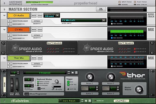
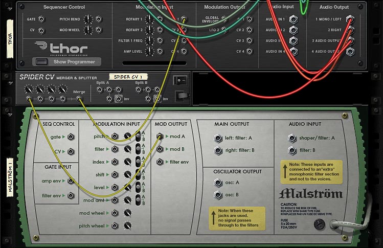
In CV tutorial 1, we set up a CV testbench that allows you to safely record CV signals as audio, so that you can view the CV waveforms that are being produced by any CV source. We will continue working with that setup:
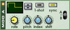
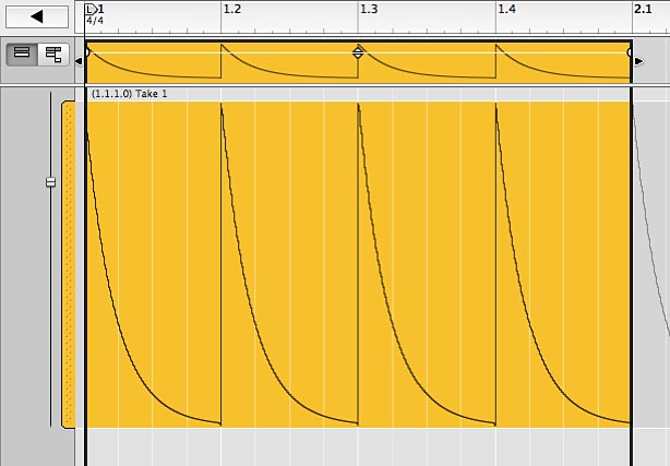
Let's use Malstrom's LFO 1, set to a half square wave (waveform 5) at full amplitude:
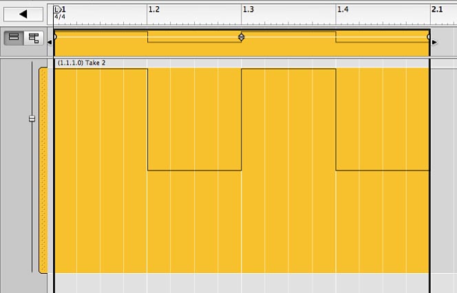
This unipolar signal produces this curve,
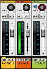
and these peak readings on the VU meters in the rack,

and mixer:
These meters are all VU meters, meaning that they respond to an RMS average of the signal over time. (See the description of "The Big Meter" in the "Hardware Interface" chapter of the Reason Operation Manual.) For most signals, such as a triangle waveform, the VU reading will be lower than the actual peak amplitude of the signal. I'm using a square wave for calibration simply because its peak VU reading happens to be the same as its actual peak dB value.
As mentioned in CV tutorial 1, I'm setting VU Offset to 0, which changes the dB scale on the channel VU meters so that 0 dB on the meters is equivalent to 0 dBFS, or digital ceiling. That is why the meters in these examples might look different from the meters in your other Reason projects.
Now let's insert a Spider CV into the signal path and vary the signal level via the Trim knob:
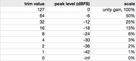
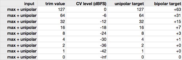
With Trim = 127, the signal passes through at full value. The following table shows how lowering the Trim value affects the signal level:
You can download this version of the test setup here:
CV-testbench2.reason.zip (zip archive of Reason song file)
Notice also that if you repeat the above experiment with a bipolar square wave (Malstrom waveform 4), you get exactly the same results, except that the meter reading remains steady instead of intermittently dropping to -inf dB. If you want a very precise calibration of these levels, you can record the CV signal into an audio clip, as above, bounce the clip to disk, and open it in an external audio editor such as Bias PEAK.
Caution: Be aware that these low-frequency or DC signals can be hazardous to your audio equipment and your ears. So in the external audio editor, be sure to turn playback volume all the way down when looking at such waveforms. And in Reason, make sure (as we have done in the above examples) that these signals never get routed to the hardware outputs.
Let's look at how to generate a constant "DC" signal using Matrix's curve generator. This is useful mostly for calibration purposes — for looking at how target parameters respond to different signal levels — or for introducing a "DC bias" to shift the centerline of an LFO oscillation up or down. Later in this tutorial, I will show how to use DC bias to convert bipolar signals to unipolar and vice versa. Other than these special situations, you would almost never need to generate a DC signal. Sending a constant value to a target parameter is exactly equivalent to changing the base value of the parameter. So usually, you would just manually change the base value of the target parameter, right?
In CV tutorial 4, I show an easier way to generate static CV signals using just a single instance of Thor. Unlike Matrix, Thor puts out the DC signal even when you are not in Run mode. A common use of DC signals is to bias a modulator signal upward when doing amplitude modulation (AM). I will get to this in a later tutorial.
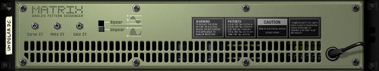
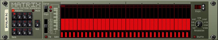
But anyway, here's how to set up a Matrix to output a maximum-value DC signal. Flip to the back of the device, find the Bipolar/Unipolar switch and select Unipolar:
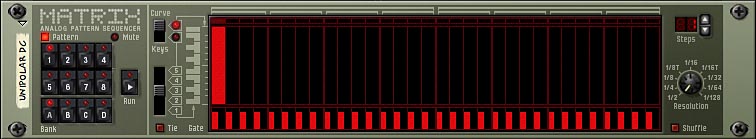
Now flip to the front, set up a single-step pattern (Steps knob at upper right) and set the first step to maximum. Find the Curve/Keys switch and select Curve:
Let's set up a second Matrix in Bipolar mode (Bipolar/Unipolar switch on the back) almost the same way, but with the first step set to maximum negative:
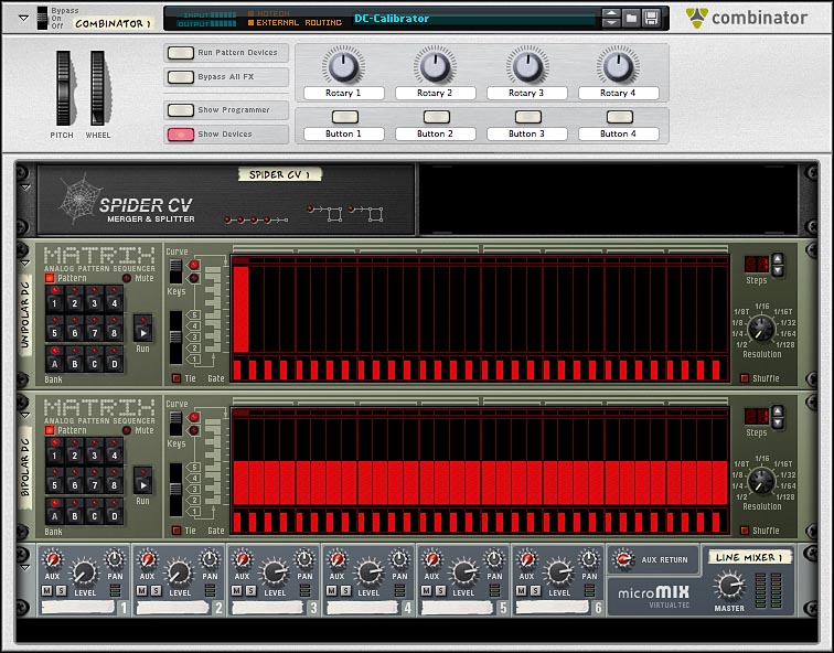
Since the Matrix device doesn't allow you to save patches, I'm going to put the two Matrices into a Combi, along with a Spider CV to let you combine the two signals. I'm also including a Line Mixer 6:2 simply as a target for CV control, to show how the Level (unipolar) and Pan (bipolar) parameters respond to CV. Here's a front view of the Combi,
and a rear view:
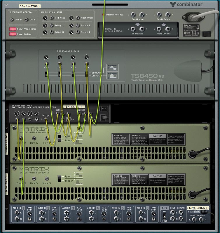
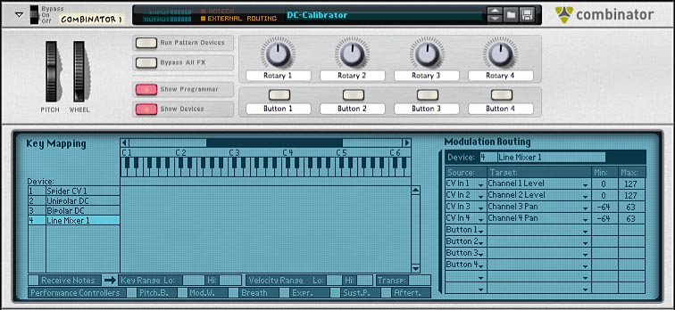
Here the "Unipolar DC" and "Bipolar DC" curve outputs go to the first two merge inputs on the Spider CV, where the Trim knobs are set to pass the signals at full value. The merge is routed to Split section on the right-hand side of the Spider and from there to the various Programmer CV Inputs on the back of Combi. Notice the Bipolar/Unipolar switches under those inputs. Here Programmer CV1 and CV2 In are set to control unipolar targets, while CV3 and CV4 In are set to control bipolar targets. Following are the target parameter routings on the Combi programmer:
In case you can't read the maze of CV cables on the Spider CV, the connections are:
You can download this entire test setup here:
CV-calibrator.reason.zip (zip archive of Reason song file)
Notice that the Matrices need to be in Run mode to send out their curve signals. As a first experiment, press the Run button on the "Unipolar DC" Matrix to send a maximum positive DC signal and notice that the "CV Mix" meter jumps up to 0 dBFS:
Now turn off "Unipolar DC" and enable "Bipolar DC", which now sends out a maximum negative DC signal. Again, the meter jumps up to maximum.
The two CV sources are added together in the Spider CV, so if you enable both Run buttons, the CV signal level drops to zero. A maximum negative DC signal exactly cancels out a maximum positive DC signal.
The above experiment shows why it's useful to think of CV signals in normalized terms. That is, think of full-scale unipolar signals as ranging from 0.0 to 1.0, and bipolar from -1.0 to +1.0. Better yet, you can think of both kinds of signals in the same -1.0 to +1.0 range, with full-scale signals peaking at 0 dBFS. (But remember also that CV signals have virtually unlimited headroom.) If you think of these signals in integer terms, the numbers just don't add up.
Now you can use the above setup to examine how unipolar targets (Line Mixer Channel 1-2 Levels) and bipolar targets (Line Mixer Channel 3-4 Pans) respond to unipolar and bipolar CV signals.
Turn on the "Unipolar DC" Matrix (enable Run) and vary the signal level by changing the curve value at step 1. Notice how the Line Mixer target parameters respond to the unipolar CV signal. Remember that channels 2 and 4 are set to respond to the inverse signal.
Now turn off "Unipolar DC" and repeat the experiment with "Bipolar DC". You will find that the target parameters respond as in the following table:
| unipolar target (channel level) | bipolar target (channel pan) | |
| unipolar signal | responds over full range | responds over full range in positive direction only |
| bipolar signal | responds only to positive phase of signal, ignores negative phase | responds over full range |
Normally, you would only connect unipolar signals to unipolar targets, and bipolar signals to bipolar targets. But as the above experiments show, unipolar and bipolar signals exist in the same -1.0 to +1.0 space, and can be mixed together.
Remember also that CV signals have virtually unlimited headroom. If the signal exceeds the range of the target parameter, however, the parameter response will be "clipped". If the parameter range is 0 to 127, you can't push the parameter below 0 or above 127.
If you vary the signal level of the "Unipolar DC" source and measure the response of the target parameters, you will get the following results:
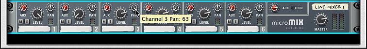
I'll spare you the details, but what I actually did was to vary the signal level using the Trim knob on the back of the Spider CV, because it is easier to read than the curve CV level on the front of the Matrix. You can read the numerical levels by hovering the cursor and reading the parameter value from the cursor tooltip:
Of course, the target parameter response, internally, need not be limited to integer stairsteps. A "smooth" CV signal could in practice provide a smooth target response. It probably depends on the device and the parameter. A topic for further investigation, maybe.
Now, repeat the calibration by using the "Bipolar DC" source only. Here, I'm using either the maximum positive DC or maximum negative DC and again controlling the level via the Spider Trim knob:
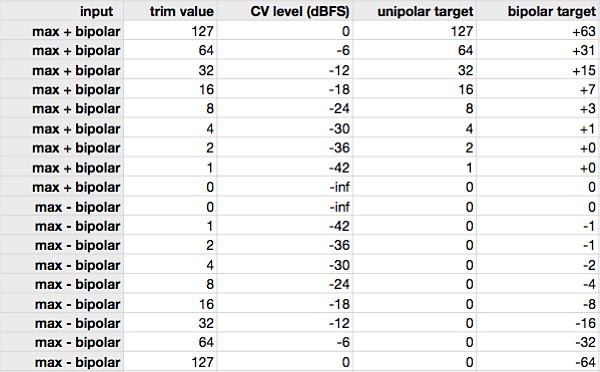
Once again, it is clearer to think of both unipolar and bipolar signals as existing in a normalized -1.0 to +1.0 range, where -1.0 and +1.0 represent full-scale, 0 dBFS levels.
Here we use a Malstrom to supply a bipolar LFO CV signal and a "Unipolar DC" Matrix (as above) to supply a full-scale, positive DC signal:
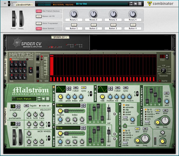
The CV connections on the back are as follows, with the Spider CV summing the LFO signal and the DC signal, and the Merge CV output going to Thor's CV 1 In as before:
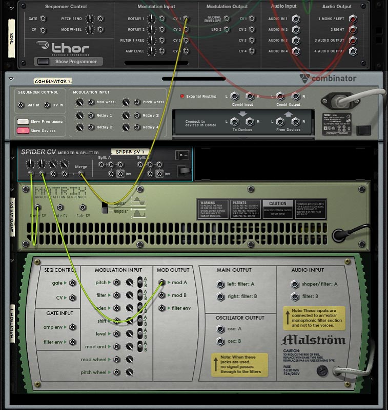
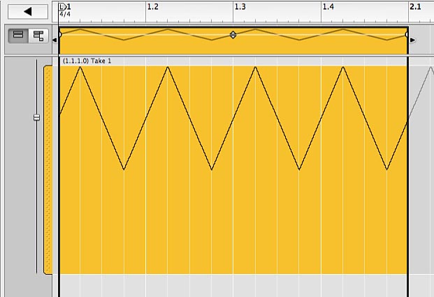
We trim the bipolar signal to -6 dB (cut its amplitude in half) and add the DC from the Matrix, also trimmed to -6 dB. In other words, we're introducing a DC bias to raise the centerline of the bipolar oscillation from zero (-infinity dB) to -6 dB. The following graph shows Malstrom's LFO 1 triangle wave converted to unipolar:
You can download the conversion setup here: Bi-to-Uni.reason.zip (zip archive of Reason song file). For an alternative way to do this conversion using Thor, see Bipolar to unipolar and vice versa in CV tutorial 4. One advantage of the Thor method is that you don't need to be in Run mode for the conversion to work.
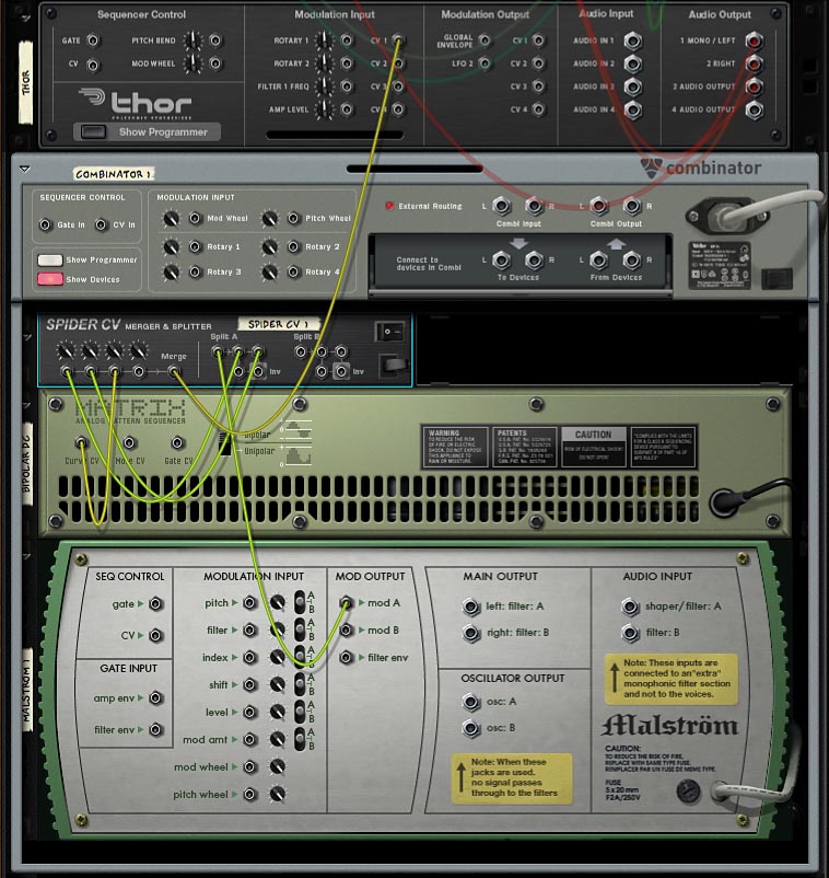
This time we want to boost the full-scale unipolar signal by +6 dB (double its amplitude, which, as you remember, does not result in any clipping) to raise the centerline of the oscillation to 0 dBFS. Then we add a maximum-level (0 dBFS) negative DC signal to bring the centerline of the oscillation down to 0 (-inf dB). How do we double a CV signal? The easiest way is to take it into Split A on the right side of the Spider and take two copies of it over to the Merge on the left, where it can be added to itself:
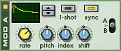
Now select Malstrom's LFO waveform 10 to put out a unipolar signal from Mod A:
The maximum-negative DC bias comes from a Matrix set up the same as "Bipolar DC" above. The following graph shows this unipolar signal converted to bipolar:
You can download the conversion setup here: Uni-to-Bi.reason.zip (zip archive of Reason song file). For an alternative way to do this conversion using Thor, see Bipolar to unipolar and vice versa in CV tutorial 4. One advantage of the Thor method is that you don't need to be in Run mode for the conversion to work.
Practically speaking, the difference between bipolar and unipolar signals is simply a matter of "DC bias" — a shift of the centerline of the oscillation by adding a positive or negative DC signal — as well as a change of amplitude.
The DC bias can also be applied at the target parameter end, simply by changing the base value of the target parameter. Then any necessary CV amplitude adjustment can be made by changing the modulation amount, e.g., by using a Trim knob at the modulation input.
In other words, the bipolar-to-unipolar (or reverse) conversion can usually be accomplished at the target end simply by tweaking the parameter base value and modulation amount. In this way, you can freely mix and match bipolar and unipolar signals.
Next: CV tutorial 3: Sequencer Control CV (control voltages)
Images in these tutorials refer to Reason 6.5 user interface elements, which are, of course, Copyright 2012 Propellerhead Software.